
| This area shows the construction and completion of the "Weatherlab I" portable weather station. This unit is constructed with portability and ease of setup in mind. It is simply a sturdy lightweight platform that supports a variety of weather equipment, antennas, lights, etc. The platform is constructed of high-pressure PVC tubing (1/4 inch wall) and designed to be put together with nothing but wingnuts. On special mounts, a complete Oregon Scientific 918 weather station, emergency light, antenna(s), hailer, and other optional equipment can be installed and configured as required. The "Weatherlab I" platform will even have an external video camera and microphone! The entire unit also breaks down and can fit in a small suitcase! This custom platform can be installed in minutes on any surface, including most car hoods, using special suction cup supports and / or straps. The storm chasing possibilities of this device are very practical. Check out the pictures and construction of the "Weatherlab I" unit on this page! Note - This page may take a while to load on some SLOWER connections! |
|
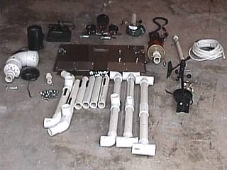
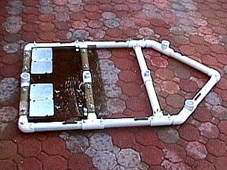
This is a picture of all the parts for the "Weatherlab I" mobile weather station spread out on the floor of my garage. This exciting project was completed just in the nick of time for the interception of tropical storm Gabrielle in September 2001. This set of parts is designed to be put together in an hour or so on top of almost any chase vehicle. This entire set of components could actually fit in a suitcase for storm chasing expeditions! |
|
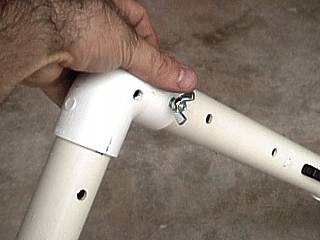
The "Weatherlab I" mobile weather station is built around a sturdy form made from 1 3/4" high-pressure PVC tubing. There are a total of 9 glued pieces with pre-drilled holes and fittings that mate and are secured with 1/4 inch bolts and wing nuts. The holes over the joints are for the supports to mount the station to a car top and the black strap guide is for support straps. This frame forms the back bone to support all equipment for this weather station. |
|
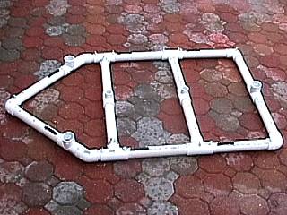
This picture shows the "Weatherlab I" PVC frame fully assembled and ready to receive weather instrumentation and other accessories. The frame is very strong and is held together with wing nuts and matching bolts. Note the "sockets" for mounting attachments and other instruments. |
|
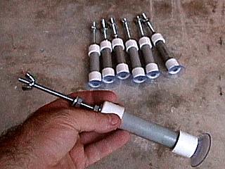
These are the 7 suction cup type supports allowing the "Weatherlab I" mobile weather station to sit atop virtually any chase vehicle. These mounts were constructed from high pressure 1/2 inch PVC tubing and affixed to heavy-duty suction cups on each end cap as well as a wing nut and 1/4 inch bolt. The bolt attaches to the main stress points (joints) of the weather station PVC frame. The suction cup does not hold the station to the car, but serves as a cushion. If the station is to be operated statically, such as atop a mobile home, these mounts should be sufficient. In heavy winds and especially when driving, these mounts behave like engine mounts reducing any vibrations caused by wind buffet. |
|
The largest piece of the "Weatherlab I" station is the so called "backplane". This is a large piece of 1/4 inch high-impact plexiglass. It is affixed to the rear two members of the PVC frame via 8 wing nuts and 1/4 inch bolts. The backplane has a mount for a rain guage with 4 bolts to attach it as well as 4 steel plates to accommodate CB, HAM, or cellular magnet-mount antennas with proper grounding. The backplane also reinforces the station and protects the vehicle and equipment from large hail. |
|
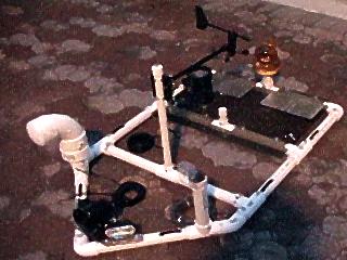
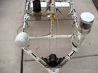
Here is a picture of the "Weatherlab I" station fully assembled and ready to be mounted on top of the chase vehicle. The front of the unit is the "point" of the PVC frame. The components from front to back are the following: The front plane is a 1/4 plexiglass nose piece containing a siren / hailer speaker and two side-shining headlamps. The elbow PVC housing is the TD / barometer sensor. The video camera attachment is on the opposite side. The central member supports the mast for the wind direction indicator and anemometer. The "backplane" with mounted rain guage and antenna magnet plates can also be seen in the rear of the unit. On the very back is the amber emergency light. When mounted atop a vehicle, the slim wires are fed into the vehicle and hooked up to a control unit and weather display computer where everything can be controlled from the driver's / chase partner's seat. This unit proved excellent in its first true "field test" in tropical storm Gabrielle in September 2001. |
|
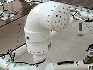
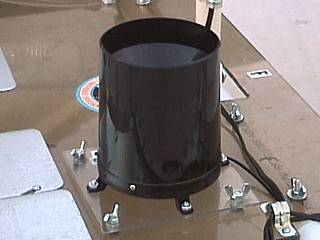
This is the housing for my dewpoint and temperature sensor on my weather station. The housing is high-impact PVC with a well-ventilated end cap on a 3-inch elbow attached to a PVC coupling for the base mount. The sensor is a small unit inside the protective housing and measures temperature, humidity, and barometric pressure. The strong housing protects the sensitive equipment inside from direct sunlight and any external threats such as debris and hail. The "elbow" can be removed via two screws and the entire housing attaches to the "weatherlab I" frame via a bolt and wing nut. |
|
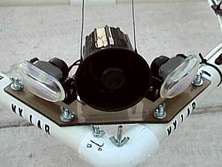
In the very front of the "Weatherlab I" unit is an attachment with two headlights and a high-efficiency loud speaker from a modified car alarm. The two headlights draw only 3 Amps each at 12 VDC and illuminate the front sides at 45 degree angles. The power is supplied via a 2-conductor trailer-type connector. The loudspeaker is simply the alarm unit from a car alarm with the oscillator removed and connections soldered on the back where ANY audio input can be fed via two conductor wire. This front piece attaches to the frame via 4 bolts and wingnuts and even has two "eye" bolts on each side of the speaker horn so optional guy wires can be attached as in this picture. |
|
This is the rain guage and its special attachements so it can be mated with the back plane of the "Weatherlab I" unit. The guage is attached to a piece of lexan plexi-glass and held to the weather station via 4 wing nuts. The studs are permanetly attached to the back-plane of the weather stattion. The rain guage is of little use when moving, but still can be used to collect rainfall measurements over a period of time when standing in one area. |
|
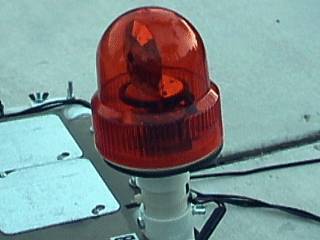
This is an amber emergency light that attaches tro the rear of the "Weatherlab I" station frame via a wing nut and bolt. A trailer-type 2 conductor connector allows 12 VDC power to be supplied as needed. The emergency light was bought at an auto parts store, had its base removed and attached to a plexiglass disk that allowed it to be attached to the PVC tube that mates with the frame of the weather station. This light is a must because it helps with visibility in poor conditions, especially with other traffic and chase vehicles. It is also great for getting past road blocks and slow traffic! |
|
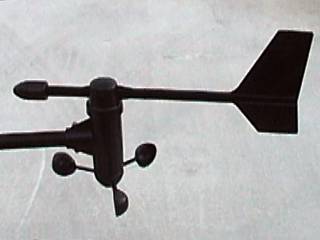
This is the wind vane and small cup-type anemometer used on the "Weatherlab I" station. It is mounted on a horizontal rod that is attached to a vertical mast that mates with the main frame of the station. The anemometer can withstand winds up to 125 MPH. |
|
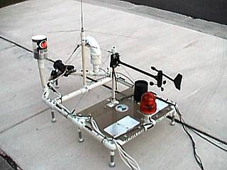
This picture shows the "Weatherlab I" portable weather station sitting on the side walk and ready to be mounted on a chase vehicle. The station here is in its "Hurricane Configuration" and was being prepared for a possible chase of hurricane Michelle in Florida in early November 2001. Note the extra-secured cables and wiring as well as guy wire supports for the antenna and wind vane mast. The antenna is a wide-band ground plane type that works best at the HAM and NOAA frequencies. Note the camera pod to the left of the antenna. |
|
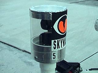
This is a picture of the moveable camera pod constructed for the "Weatherlab I" system. The camera pod is simply an X-10 CCD color NTSC camera and microphone attached to a base that swivels 235 degrees left or right via a modified servo from a hobby shop. The housing is constructed out of PVC and clear plexiglass. Aluminum tape covers the unit to prevent extra sunlight and glare from affecting the camera operation. The housing also can be removed via two large screws. Note the "Skywarn" logo. The number "5" is for easy mounting reference. A remote control unit attached with a 2-pole trailer-type connector controls the camera motion, while a separate cable handles the AV signals. This camera offers a superb "birds eye" view from the top of the chase vehicle! |
|
This is the rear view of the "Weatherlab I" station from above showing the back plane, anemometer, wind vane, emergency light, rain guage, and extra antenna mounting plates. The back plane is UV resistant, high-impact plexiglass and attaches to the main frame of the station using 8 bolts and wing nuts. Wire and cable guides are also used on the back plane. Note the mounting area where the mast for the wind sensors mates with the main frame of the system (where the square hole is in the back plane in the upper center of the picture). |
|
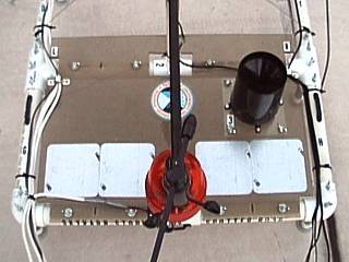
This is the front view of the "Weatherlab I" station from above showing the headlights, loudspeaker, antenna, dewpoint sensor, and camera pod. The back plane of the unit is in the background with the rain guage visible to the upper left. The antenna mounts to the main frame via a wing nut and bolt, center, and the camera is to the right, the temperature / dewpoint sensor to the left, and headlights / speaker unit in the very front. Note the "cross bars" from left to right where the antenna and mast for the wind instruments mount to. |
|
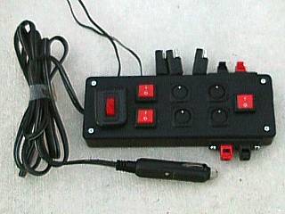
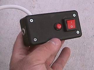
Power for the entire "Weatherlab I" station is supplied by a regular cigarette lighter adapter for 12 VDC car power. The main design of this system is to provide maximum versatility and power with minimal amperage drawn from the chase vehicle's 12 VDC system. The control box has a cigarette lighter plug with 20 A fuse and long heavy duty cord, an illuminated main switch, two red switches for the WX computer and video system, three black switches for the 12 volt trailer-type connectors (One for the emergency lights, one for the headlights, and another for an extra auxiliary supply), and another black switch for the alarm oscillator (the oscillator was removed from the car alarm speaker and placed inside this unit). The red switch to the right is to select the loud speaker output from alarm oscillator or auxiliary input. When switched to auxiliary input, the alarm loudspeaker can accept any audio signal, such as a radio or PA output, via spring loaded inputs. The alarm oscillator / audio output is also a spring loaded speaker-type connector. The three swiched 12 VDC outputs are 2 pole trailer-type connectors and the other 2 (camera and WX computer) are 12 volt wires terminated with a standard adapter jack. The enclosure is a small RS project case. |
|
This is the control for the moveable camera system on "Weatherlab I". One 12 VDC output from the main power module plugs into the standard adapter plug in the left side of this unit. The white cable is the power cable leading up to the motor controls of the camera pod. The large switch to the far right controls the direction of swivel and the push button allows the move of the camera to be carried out in that direction. The second power adapter for the camera itself and AV cabling attaches to the other side of this module (not visible to the far right) via another standard connector. |

|
This is a picture of the main weather "brain" of the "Weatherlab I" portable weather station. This is the Oregon Scientific model 918 Weather Station. All the temperature, pressure, and rain-fall sensors terminate via cabling at this device. The WX computer here can display temperature, dewpoint, barometric pressure, rainfall rates, wind velocity, wind direction, and derivatives of each such as wind gusts, and different units of each measurment. The WX comnputer comes complete with battery backup power, a fully functional alarm clock, even weather forecasting! |
|
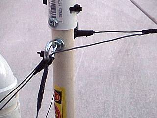
Another important feature of the "Weatherlab I" prototype is the ability of installing extra "strengthening" via guy wiring. The antenna mounts and mast for the wind instruments have "eye" bolts for fastening steel wiring if the station will be used in very severe winds. In this picture, we see the guy wiring supporting the antenna for HAM communications while preparing for a hurricane intercept project. Such extra support is a MUST for strong winds. |
|
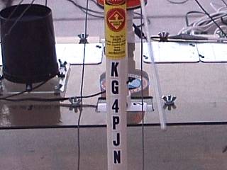
Here is a picture of the antanna support mast for the HAM ground plane type antenna used on the "Weatherlab I" system. As with many amateur radio licensees, I proudly display my "KG4PJN" call sign in plain view. Note the warning label above signifying "watch for wires". |
|
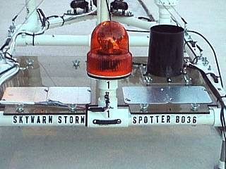
On the back of the "Weatherlab I" unit, I also display a label saying "Severe Storm Spotter B036". The "B036" is my Skywarn spotter ID for Broward County, Florida. Such labeling is not for looks, but to CLEARLY indentify to anyone who you are and what you are doing. This reduces intimidation to the general public who may not be familiar with storm chasing equipment as well as a good non-suspicious attitude from police and other authorities. |
|
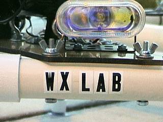
On the front of the "Weatherlab I" unit, on each side just below the mount for the hadlight and hailer speaker unit, the label "WX LAB" is affixed to the main frame of the station. The side of the station also has the warning label saying "CAUTION" affixed to the side frame. Other numbering and lettering along the frame and top are for assembly and reference information, and not visible when the unit is assembled and atop a chase vehicle. Note the headlight as well as mounting hardware for the front headlight / hailer unit in this picture. |
|
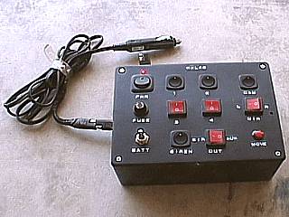
This is a picture of the front panel of the re-designed control console for the weather station. On the left is the main power controls (note the power input plug) consisting of a main power switch, fuse, and battery power switch (shown "on" in this picture). Two internal 6 volt emergency lighting batteries are in series for 12 VDC, and are able to run the entire unit detached from the vehicles 12 volt system! The switches labeled 1 and 2 are for the lighting 12 V non-polarized outlets (2-conductor trailer type connectors). Switches 3 and 4 are for the 12 V adapters to power any 12 V unit (weather station 918 sensors console and HAM radio, for example). The "siren" switch turns on or off an internal oscillator for the audio output to the loudspeaker on the "weatherlab I". The two place switch to its right selects the "siren" output or even an "aux" audio input, such as from a radio or microphone amplifier output (you can "hail" people in this way). Finally, to the right, are the X10 color camera controls. The camera power switch is at the top and pan direction controlled by the two place switch below it. To move the camera, first set the direction to pan and push the small pushbutton along the bottom to move the camera (field of movement is about 235 degrees). All power and control outlets are at the rear of this unit. |
|
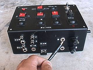
This is a view of the rear of the main re-designed control console for the weather station. It is custom made for the connections to the weather instrumentation, lights, loudspeaker / siren, even the color video camera package. In the picture here, a plug with a standard DC adapter is being held to one of two compatible outlets. Note the X10 camera RJ-12 adapter and AV inputs / outputs (both RCA and PHONO types are provided). All inputs / outputs / power adapters are controlled via the switches on the front panel. |
HTML File "wxlab.htm" - Developed By Chris Collura
To Return To The HOME Page Of This Site Click The "INDEX.HTM" Link Here!