
| This area shows yet further improvements to the original Tesla coil design. Here better and more reliable components were used in this stage in order to get a working Tesla coil. The tesla coil project is aimed mainly at the scientific and Tesla coiler community. I intend to use my Tesla coil for lightning demonstrations and entertainment. Note - This page may take a while to load on some SLOWER connections! |
This section includes yet more modifications and enhancements to the Tesla coil design shown above. The main and most pressing problems from the second redesign of the original coil were capacitor and insulating problems, which caused a failure of the coil in just seconds, before any real "spark testing" could even be done. The third design here replaces most high voltage wiring with heavy-duty RG-58 RF cable. Also the primary coil was elevated an inch above the original wood supports with heavy duty 1/4 inch polycarbonate plexiglass. Two chokes, made of #22 AWG magnet wire of about 100 turns each over 1" PVC pipes, were mounted on each output of the neon sign transformer. This should prevent damage to the NST from RF voltages that cause magnet wire enamel to fail. The power supply for the NST and RQ spark gap cooling fan was also made separate, with two PC plug adapters (with an AC line filter for the NST supply) so that the NST supply can use 0-120 volts without affecting the RQ cooling fan, which was also changed to a 120 VAC 65 CFM cooling fan. The RQ gap was also requilt in a 1/4 inch plexiglass box, using stainless steel 3/4 inch tubing electrodes from an aircraft supply company instead of copper (won't oxidize). The "pass through" HV wires from the base of the unit to the primary were also farther protected with insulation, and the center "hub" for the secondary was sealed at the bottom with a circular plexiglass bushing. As for the most important and rather frustrating component, a 0.0125 uF capacitor was made from 5 doorknob type capacitors ordered from eBay rated at over 30 kV (2500 pF) each in parallel.
Lessons learned - If you can, try to use doorknob or Maxwell pulse type capacitors. This version of this Tesla coil finally delivered sparks over two feet long when tapped at 9 turns on the primary. A handheld fluorescent tube was illuminated when within ten feet of the coil!
|
The diagram above is the schematic for my third Tesla coil design step. In this configuration, the AC power input was split into two separate paths. One path powers the 12,000 volt 60 mA neon sign transformer and the other path a 120 VAC 65 CFM cooling fan for the new and redesigned RQ spark gap. This allows the fan to run at a constant speed and the high voltage power supply to be separate so a variac can be used. The NST supply also has a line filter (from a PC power supply plug) and both lines are equipped with small neon power indicator lamps. The primary circuit of the tesla coil assembly is series connected with the 0.0125 uF tank capacitor. The redesigned Richard Quick type spark gap is parallel connected in the circuit. The secondary is connected to RF ground at one end (not the mains ground, ofcourse) and the other end is the output HV terminal for the coil. |
|
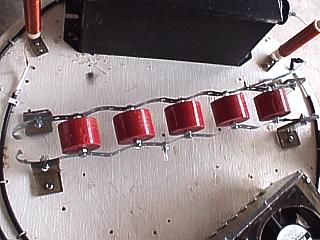
This is a picture of an array of five doorknob type HV pulse capacitors each rated at 30 kV with a 2500 pF capacitance. Five in parallel yielded the 0.0125 uF needed for my coil to operate efficiently. The doorknob capacitors had a threaded 1/4 inch screw bolt terminal and were easily assembled into an array by perforated metal strips which served as the power "bus" for the capacitors. The entire array is raised and insulated from the wooden Tesla coil base by plastic "L" brackets made from strips of 1/4 inch plexiglass that were heated and bent. the holes in each metal strip not only made mounting easy, but allowed electrical connections to be made right to the capacitors. Note the safety spark gap to the far left formed by simply bending the metal strips. This safety gap should protect the capacitors from any flashover while also protecting the NST itself. |
|
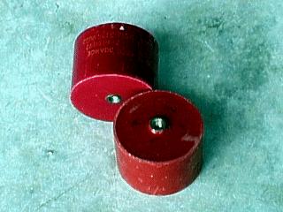
This is a picture of the high voltage doorknob capacitors I decided to use with my Tesla coil. These are high voltage rated (30 KVDC) at 2500 pF each. These are one of the best types of capacitors you can use for a Tesla coil. They are rugged, compact, relatively inexpensive, and can handle the high voltage RF currents in the Tesla coil circuits. I obtained 10 of these from an EBay online auction for about 5 dollars a piece. My coil needed a capacitance of about 0.012 uF (12000 pF) so five of these units in parallel gave me a total of 0.0125 uF (5 x 2500 pF). The 30 kV was a great safety margin for my 12 kV NST. |
|
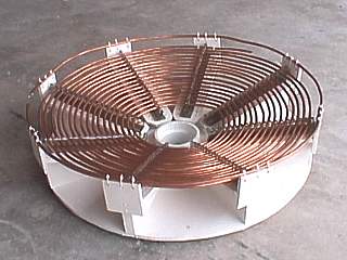
This is a picture of the new tesla coil primary after modifying the primary coil supports. The coil form is the same, but special supports made from 1/4 inch-thick plexiglass were glued to the previous supports for the 1/4 inch copper tubing using silicone. When fully dried, the copper tubing for the primary coil was re-wound where the tubing can fit snug into the grooves. This raised the copper about in inch higher, but eliminated any chance of arcing to the carbon or moisture in the wood as what happened in the last attempt at building this tesla coil. The center mount for the secondary also had a piece of plexiglass to close off the "hole" below it, thus sealing any secondary mounted to it. The strike rail remains attached the same way as the wood unit will not need to be protected from the RF or mains ground. |
|
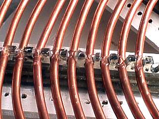
Here is a closeup of the new primary coil after plastic "risers" were installed. The risers were eight upside-down "T" shaped pieces of 1/4 inch-thick plexiglass with grooves about 1/4 inch wide cut in the top edge. When the primary of 1/4 inch bare copper tubing was re-wound, these grooves provided support and spacing for the primary. A gentle hammer tap was needed to get the tube into the groove, which was also sealed with silicone. Note the original holes where the wire ties were used to hold the primary during the last attempt, which had arcing to the wood. primary has a total of 17 turns. |
|
Here is a view of the bottom of the linear RQ spark gap assembly. There are six electrodes made of 3/4 inch OD stainless steel tubing from an aircraft metals supply company. They are high temperature and will not oxidize redily like copper tubing. In this design attempt, the six electrodes are tightly fitted through a hole in one side of the box, and have their other end resting in a 1/8 inch deep 3/4 inch recess in the 1/4 inch thick plastic. Silicone cement keeps them from moving. Although visually appealing, the spark test caused oxidizing of the plastic and silicone forming a carbon deposit which would short the gap. This configuration was disassembled and will be redesigned with long bolts that will secure a shorter version of the tubing away from the sides. |
|
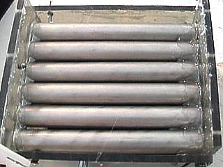
This is a picture of the new linear RQ spark gap. This is a special version of the Richard Quick design where the electrodes are in a row rather than in a circular fashion. In the design here, 1/4 inch UV filtering plexiglass forms the box with the 4 inch 120 VAC 65 CFM vent fan built into the unit. The electrodes are siz 3/4 inch OD stainless steel aircraft quality tubes. Air flows into the bottom, through the electrodes, then exhausts out the fan at the top. This was the first attempt at this kind of spark gap. In this attempt, holes were drilled in the plastic to hold the tubes in place. The design is good, but arcing close to the edge of the tubing can carbonize the plastic and short the gap. |
|
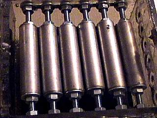
This picture shows the second attempt at designing the electrodes for the redesigned linear RQ spark gap. In this attempt, the electrodes are shorted and in the center of the spark gap housing, supported by long bolts and washers. This will ensure that no arcing will occur near any plastic as well as enhance cooling from the quench fan. This type of gap is also fully adjustable with a wrench because the supporting bolts are mounted in a slot rather than a drilled hole in the plastic. |
|
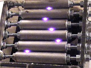
In this picture, an arc test is being performed on the linear RQ spark gap. This was done by hooking it up directly to the output of the 12 kV neon sign transformer. Note that the arcing is not at the edges of the electrodes and confined away from the plastic or any other areas. This indicates that the spark gap is properly aligned. The arcing with a full capacitive load will ofcourse be much different, probably filling the entire space between the electrodes with parallel arcs. |
|
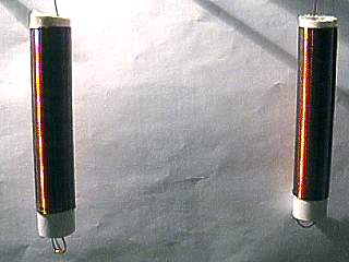
For this version of my tesla coil, two RF chokes are required for filtering out high frequency current from the outputs of the neon sign transformer. There are two chokes, one for each high voltage output on the NST. Problems with some tesla coil projects involve the RF frequencies that degrade the HV insulation on NST secondaries, causing the NST to burn out. Chokes filter the RF, but still allow the 60 HZ to pass through unhindered. The two chokes shown here each have roughly 125 to 150 turns of #22 magnet wire on a 1 inch PVC pipe. They are 5 inches long, with 4 inches winding length and are treated with polyurethane varnish. Winding them closely was very similar to the tesla secondary, just much smaller! |
|
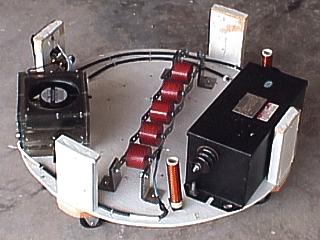
This is a picture of the final design Tesla coil base before installing the primary assembly and secondary support. The capacitors can be seen in the center of the unit, and are 5 30 KV doorknob type capacitors supported in a metal strip bus. The modified RQ type spark gap is to the left, and NST to the right. |
|
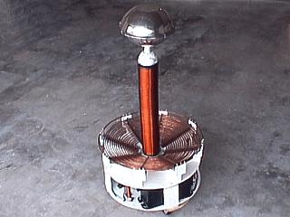
This picture shows the completed Tesla coil ready to be tested. The primary coil with its support and structure is attached to the base using heavy wood screws. The secondary is fully detachable and made so other secondaries could be swapped. The base of the secondary has a quick release screw for the "RF ground" wire. The primary also has an adjustable tap via an alligator clip for tuning. |
|
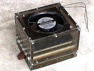
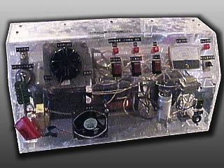
This is a picture of the control unit I am using to power my Tesla coil. This was originally a science project from when I was in High School. I have since redone this project, originally in a wooden box. The new design is in a clear 1/4 inch plexiglass (Lexan) box custom formed by heating and bending and held together with screws and plastic cement. This control box has a variac with both 0-120 VAC and fixed 120 VAC outputs. The unit also has a built in oil burner ignition transformer for 0-10000 VAC as 23 mA, a microwave oven transformer for 0-2500 VAC at 500 mA, and 12 Volt transformer with DC rectifier for 0-12 VDC at 10 A, all controlled by switches and the variac. The voltmeter to the right is for the DC voltage. The unit is also equipped with a PC cooling fan and indicator alarm. A key switch, left, prevents unauthorized use of this control unit. For my Tesla coil, the spark gap quench fan is plugged into the fixed 120 VAC outlet. The other connection to the NST, is plugged into the 0-120 VAC variac output outlet. From a convenient distance, the Tesla coil can be operated from this control console using extension cords. Works out great for demonstrations. |
HTML File "tcpart3.htm" - Developed By Chris Collura
To Return To The HOME Page Of This Site Click The "INDEX.HTM" Link Here!