
| This area shows modifications and re-powering of my first Tesla coil for higher output power with improvements over the original design. The Tesla coil project is aimed mainly at the scientific and Tesla coiler community. I intend to use my Tesla coil for lightning demonstrations and entertainment. Note - This page may take a while to load on some SLOWER connections! |
This section includes modifications and enhancements to the Tesla coil design shown above. The original coil was redesigned and rebuilt with a larger power supply, a 12,000 volt at 60 mA neon sign transformer, adjustable RQ spark gap, MMC capacitor array, copper tubing primary, and best of all, a larger secondary coil wound over thin 4 inch polyethelyne with the ability to change the secondary via a quick connection on the new Tesla coil base. Both the original and new secondary coils are adapted to mate with the new Tesla coil. This design was not spark tested because of problems encountered while testing the spark gap performance before connecting and secondary.
Lessons learned - First of all, don't use WOOD for your Tesla coil primary support / form. If you have to use wood, make sure it is very dry and / or that the bare copper of the primary remains on a plastic support at least 1/2 inch from any wood. I found out that plywood is a very good conductor at high voltages and directly shorted my primary to mains ground! Maybe this happened due to moisture in the wood, the humidity here in South Florida rarely is less that 90 percent! When using an MMC array, make sure a far overkill is used in voltage ratings. My MMC was not cheap and lasted less than the plate cap design on the first Tesla coil attempt ... 20 kV is not enough, especially when a 12 kV RMS peaks at 17 kV for 120 kV input. For a 0-140 volt variac control as an input, that's up to 19.7 kV peak. A simple spike could easily exceed this, that's what blew my caps. I will try a 30 kV or even a 40 kV array. If that is not sufficient, maybe a rolled HDPE sheet capacitor at 40 kV rating will be better.

|
The diagram above is the schematic for my redesigned Tesla coil. The AC input runs through a 120 VAC line filter (from a PC power supply plug) to a 12,000 volt 60 mA neon sign transformer. The primary circuit of the tesla coil assembly is series connected with the 0.01 uF tank capacitor. The Richard Quick type spark gap is parallel connected in the circuit. The secondary is connected to RF ground at one end (not the mains ground, ofcourse) and the other end is the output HV terminal for the coil. The RQ spark gap fan is powered by a small 12 VDC cooling fan running off a small 12 VAC step-down transformer and a rectifier to power the fan. A small neon power indicator lamp was also added in this design step. |
|
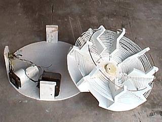
During the redesign of the original tesla coil project, the primary structure is removed from the base of the unit via a jig-saw cutting around the supports. The thin plywood was left on the supports for the new primary coil. The RQ spark gap, oil burner transformer, and wiring are still on the base. Note the plate capacitor has been removed, a multiple mini capacitor (MMC) array will replace it in the new design. |
|
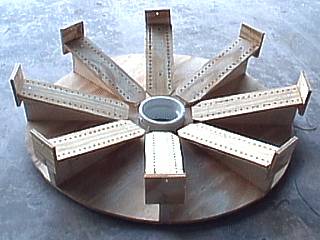
This is a picture of the wood form for the new primary coil. The supports will be a "top mounted" design rather than running through drilled holes. This reduced the frustrating splitting and splintering of the thin plywood. The center hub is a PVC adapter to accept the secondary coil. The strike / RF ground rail will run around the unit on the outermost supports. Each of the eight pieces is drilled so that the primary coil can be attached to it using plastic wire ties. |
|
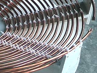
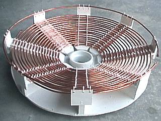
This is a closeup of the completed primary coil structure. Note how the primary conductor, a 1/4 inch bare copper refrigeration tube, is attached to the surface of each of the eight radial supports using plastic locking wire ties. The grounding rail runs around the edge supports. Note the break in the ground / strike rail to the upper right. This cone is at roughly a 20 degree angle and there is 17 turns of tubing spaced at about 1/4 to 1/3 of an inch. |
|
The redesigned new primary coil is now painted white with an oil based, moisture shielding paint and the 1/4 inch copper tubing is being wound. In this picture, the first 50 feet of tubing is done. About another 15 feet or so was needed to complete the coil. The tubing solders very well and was easy to join with the rest of the required tubing. |
|
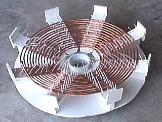
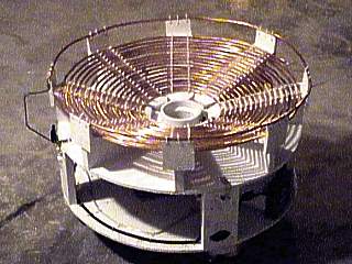
This is the redesigned primary coil in its completion. It is an inverted cone of about 20 degrees of about 17 turns of 1/4 inch copper refrigeration tubing spaced at 1/4 to 1/3 of an inch. The RF ground / strike rail is another short section of non-continuous tubing roughly 2 inches above the outhermost turn of the primary. An alligator clip will allow tapping into any location on this primary coil, such as the more common turn 12 or turn 15. The center hub has a mount for the secondary, allowing for easy disassembly, storage, or even adding another secondary type in the future. |
|
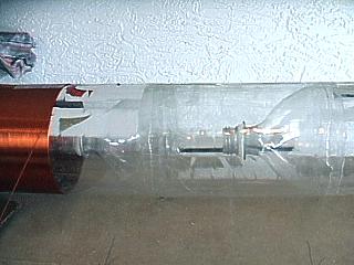
Here is the new secondary coil being wound on the winding lathe. The major difference between this coil and the original is that extremely thin polyethylene is being used opposed to PVC tubing. This type of material is best for minimal RF loss compared to PVC. Note that 2 liter soda bottles are being used! Cutting off the base of each bottle and inserting the top formed a tight fit which was sealed with PVC cement. Most of the labeling, also plastic, was removed from each bottle prior to winding it with AWG 22 enameled magnet wire. The bottle tops formed a reinforcement for the thin clear-plastic used in this form. |
|
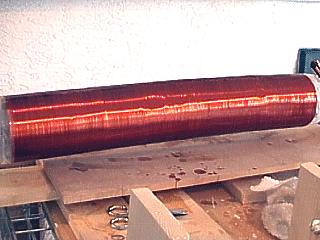
The new secondary coil, exactly 4 inches in diameter and 24 inches long, is finished being wound with #22 magnet wire and has the first coat of polyurethane varnish in this picture while still on the winding lathe. The varnish will actually strengthen the coil on the thin polyethylene plastic of four 2 liter soda bottles. This new coil will be slightly bigger than the original secondary, which was on thick PVC tubing around 3 1/2 inches in diameter. Winding the magnet wire on such a form was more difficult than winding it on PVC, but is well worth it due to the higher RF efficiency of such material. |
|
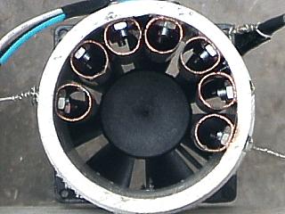
The Richard Quick type spark gap used in this project also has been slightly modified for the new tesla coil design. The original had a copper electrode, a 3 inch long piece of copper tubing, which was in the bottom of the unit in this picture. This piece, which served as a safety gap, was removed and placed with the other six electrodes. The new spark gap has a total of seven copper electrodes. Also, the wires going through the PVC and soldered to the electrodes were changed to that they attach to the nuts holding them on the outside instead. More spark gaps means better frequency switching for the tesla coil. |
|
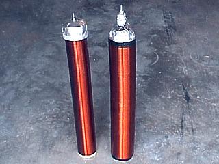
Here are the secondary coils used in this project. The one on the left is the original secondary used in the original coil design and is PVC based at about 3.5 inches. The new coil is to the right, and is larger at 4 inches. Both have a winding length of 24 inches and are wound with roughly 900 turns of AWG 22 enameled magnet wire. The new coil is made of lightweight and thin polyethylene plastic from four 2-liter soda pop bottles end to end. The end bottle forms the top of the new secondary and is coated with aluminum foil forming the top terminal. The bolt on the top of each secondary is for a top load attachment. The new tesla coil has the ability to remove the secondary for storage purposes, as well as swapping each secondary if needed. The base of the new secondary has a wood chock to mate it with the secondary mount of the new tesla coil. |
|
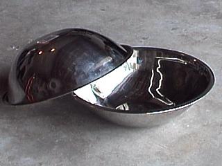
One of the best and inexpensive ways to construct a good tesla coil top load is out of two metal salad bowls like the ones in this picture. They can easily be drilled and either bolted or welded together and attached to the top of the tesla coil secondary. The two bowls here are roughly 12 inches in diameter and were very inexpensive at my local KMart. |
|
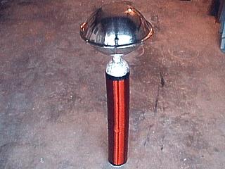
The completed new and redesigned secondary is shown here with the top load installed. The top load, which is two metal salad bowls joined together, was bolted to a soda bottle cap, which easily attaches to the top of the secondary unit and also can be removed if needed. The entire secondary rig stands about 3 feet tall. |
|
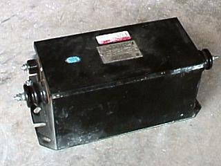
Here is a picture of the neon sign transformer (NST) to be used with the redesigned tesla coil. It is a big step over the 10 kv, 23 ma oil burner transformer with an output of 12 kv at 60 ma. This should increase the power of the tesla coil from 230 watts to about 720 watts, over three times as much. The only down side was obtaining such a device. The unit here was a nearly new model from Franceformer, a good transformer choice. The unit was not cheap either, at 85 dollars from a local sign company. Some places will give away such units, especially if they are broken, or depending on the area where you live. 60 ma models are much harder to find than the 30 ma models, especially in warmer climates (more current is needed for signs operating in cold weather). Higher power is also needed to drive larger sparks on a tesla coil. The rule of thumb is, the 9 to 12 kv range is fine at 30 ma, but 60 ma is a much better choice, if available. This unit also is great for building a jacobs ladder, where and arc climbs up two spaced metal rods (remember Frankenstein)? |
|
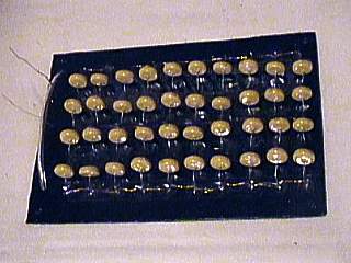
Here is my attempt at building a MMC (Multiple Mini Capactior) array. There are a total of 40 capacitors, each rated at 10 kv at 0.001 uF. The array consists of 20 parelleled sets of 2 of these capacitors in series to bring up the voltage rating to 20 kv at 0.01 uF. The capacitors are ceramic disk type and are mounted on a piece of polycarbonate sheet with drilled holes. The ends are connected on the other side with #22 bare copper wire and soldered in place. The parallel connection to the entire array is to the left of this picture. Black electrical tape was also used to cover the exposed metal on the bottom of the unit. |

|
Here is the components installed in the unfinished base of the new tesla coil. The 12 kV, 30 mA neon sign transformer (left), MMC array (center), RQ spark gap (right) and electrical connections can be seen in this picture. Note that all high voltage wiring is covered in clear plastic tubing, similar to aquarium air lines. Also, not visible in this picture, a dolly with four wheels was attached to the bottom of the base. The NST was quite heavy and the entire unit is great when wheels are installed. To the far right, the power input is visible on the support stud. A green neon power indicator light was added above the power input connector. |
|
The finished tesla coil base for the redesigned coil is shown here. The wheeled base and components support the primary coil which can be interchanged because the center has a mounting hub with a screw terminal to connect the RF ground. On the left, the strike / RF ground rail connects to another terminal so that the RF ground can be hooked up to an appropriate ground OTHER than the mains ground. Although it may look nearly perfect, this base had a MAJOR problem ... The bare primary, sitting ON the wood supports, conducted electricity really GOOD, and shorted the system, even blowing a few snubber caps on the MMC array! This was before the coil could even be "spark tested". Wood is a good insulator, but not when above the kilovolt range. Carbonizing is what lowered the wood resistance. The next design will have thick plastic to hold the primary above the wood surface. |
|
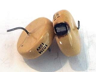
Each capacitor in a multiple Mini capacitor (MMC) array is called a snubber capacitor. After constructing the 0.01 uF MMC array (At a theoretical 20 kV rating) and powering it up to test the primary, NST, and spark gap performance ... Flashover! The high voltage in the primary jumped from the metal contacts on the MMC unit directly to the wood structure of the tesla coil base ... I guess wood is an excellent conductor at 12 kV plus. Each capacitor started to flashover and fail like the one in this picture. A very disappointing failure after time and money spend building the MMC. Maybe I will try three or four in each series pack instead of two ... Or try another design. The blown cap is obvious to the right, a good capacitor is on the left. |
HTML File "tcpart2.htm" - Developed By Chris Collura
To Return To The HOME Page Of This Site Click The "INDEX.HTM" Link Here!